
So you want to 3D-print a camera accessory like a lens adapter, extension tube, or a custom lens? You’ll need a lens mount design to go along with that!
We’ll clone the required dimensions from the mount found on a lens (for ‘male’ mounts) or camera (for ‘female’ mounts). One way to get an example of both the male and female mount at the same time is to buy an extension tube for your desired mount, e.g. I’ve found the ones from Meike to be good. Avoid tubes with plastic mounts as these are less accurate and may have draft angles that make them difficult to measure. Get a tube that has electronic contacts (for autofocus) so that you can use the dimensions of those as a reference as well.
You’ll need a pair of calipers for measuring the lens dimensions.
For this example I’ll show the process of modelling a Sony A lens’s ‘male’ mount using Fusion 360.
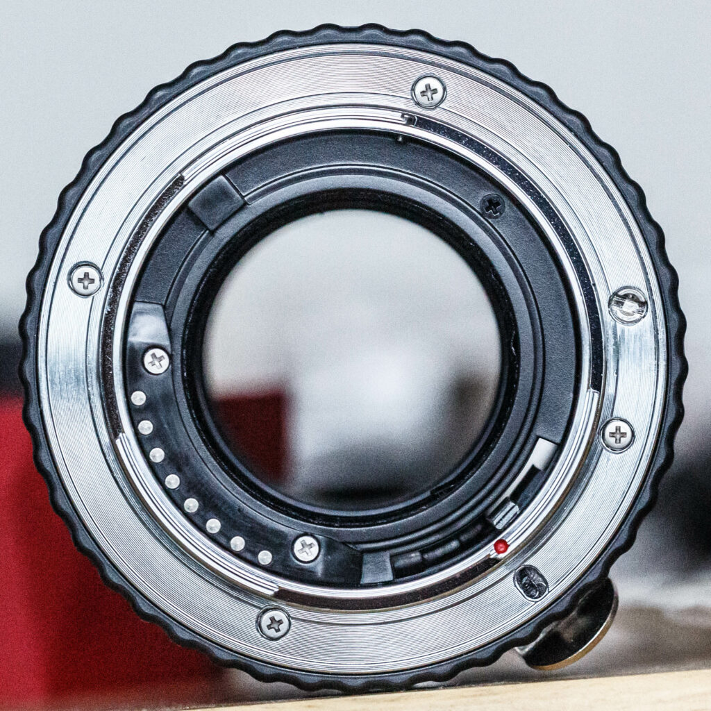
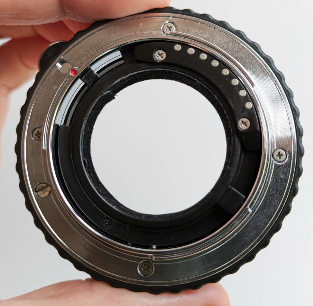
Start by taking a reference photo of your lens mount. Be sure to align your photo straight-on with the mount so that the image isn’t skewed. If you can stand far away from the mount and zoom in when you take the photo this gets you closer to an “orthographic perspective”, which means that features won’t appear to erroneously grow larger when they’re closer to your camera.
Here’s my shot:
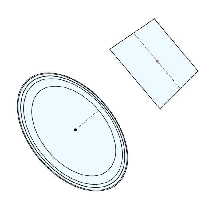
Insert this photo as a canvas on the XY plane of your design, and drop a sketch on that same plane called “Mount” to hold the basic mount dimensions. We’ll start by mapping out the diameters of the circular features of the mount. The easiest mount dimension to measure is this one, which is the ring that laterally locates the lens within the camera’s mount, measure it with your calipers:
Draw a circle at the origin with that diameter, I measure 49.95mm, but I’ll round this down to 49.90mm because I expect my 3D print to only manage a +-0.05mm accuracy and I don’t want to exceed the diameter of the original.
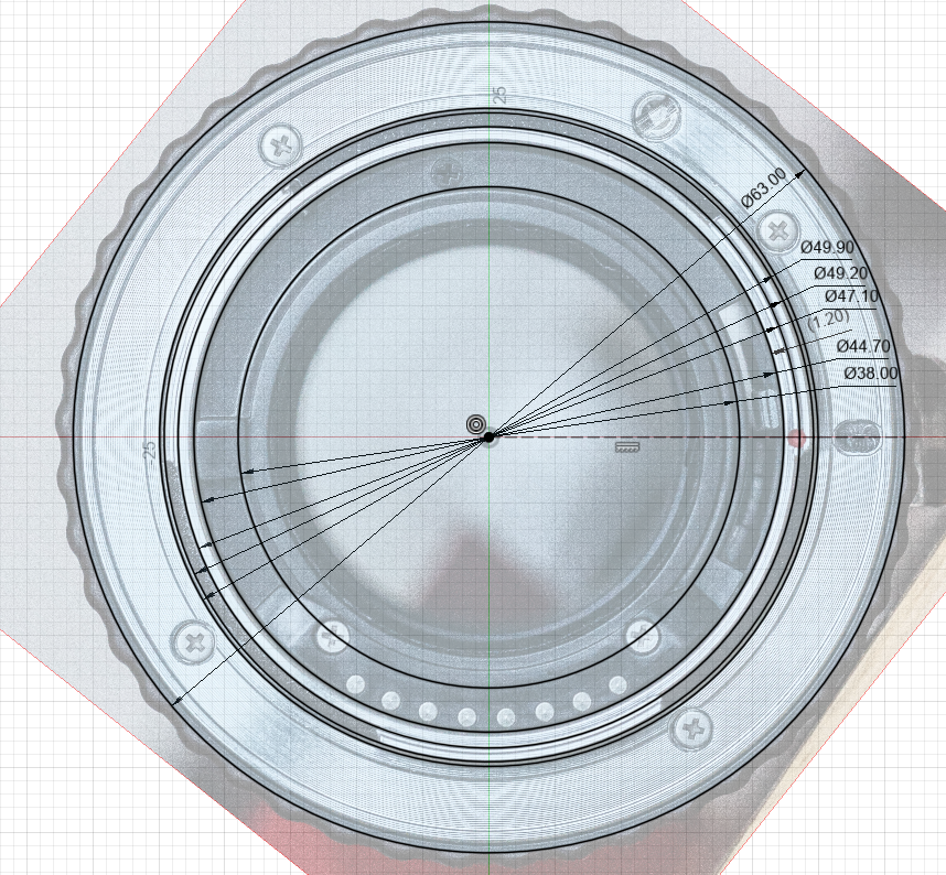
Now with the sketch still open, you can edit the canvas to scale and align it with this measured circle. Rotate the canvas to put the locking pin slot horizontal. Measure more diameters on the adapter with calipers and add circles for them, from largest to smallest I find:
- 63.00mm – The outer body diameter of the mount. If we exceed this too much we might overhang features on the camera like lens eject buttons or damage features like weather sealing O-rings. I’ve pushed this a little up from my reference adapter in order to give me more wall thickness between the outer edge of the locking pin slot and the outer wall of the adapter.
- 49.90mm – The diameter of that lateral locating ring we drew first
- 49.20mm – The diameter of the outer edge of the bayonet lugs, this is always comfortably smaller than the lateral locating ring, because the lugs have to penetrate deeper into the camera than that ring does!
- 47.10mm – The outer diameter of the “nose” cylinder that the bayonet’s lugs attach to. This needs to be small enough for the bayonet lugs from the camera to not rub against it, so we can’t exceed this dimension by very much.
- 44.70mm – The inner diameter of the nose cylinder. This diameter is important because we’ll use it to define the keep-out zone for avoiding colliding with features that lie inside the nose, like the electronic lens contacts and aperture levers. But we want to have a total wall thickness for the nose of not smaller than 1.20mm for strength when 3D-printed (so we may need to push the outer and inner dimensions a little bit to achieve this).
- 38.00mm – We arbitrarily pick this diameter for the inner aperture that the light will actually pass through. If this is too constricted we risk clipping the corners off the image for lenses whose rear pupil is very distant from the camera. For image-space telecentric lenses or very long extension tubes, this circle will need to be wide enough to encompass the entire sensor, i.e. 43.3mm for 36x24mm full-frame sensors, or 28.9mm for 1.5x crop sensors. Or else you can reshape this aperture to be rectangular to match the aspect ratio of the sensor.
We’ll use the locking pin slot as a reference for the radial placement of features, so draw a construction line that goes through it. Here’s how my Mount sketch ended up:
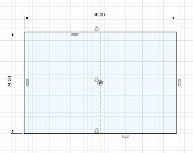
It can be handy to have the camera’s sensor modelled as a reference too, so I create an offset plane from the mount to put a sketch on for this. The offset needs to be set to the Flange Focal Distance of the mount, the distance between the flat surface on the camera’s mount and its sensor, which for Sony A is 44.50 mm. Ensure the orientation of the sensor relative to the locking pin matches the orientation in your own camera’s mount, and the sensor is centred on the origin:
Create a sketch on the same plane as the Mount sketch to define the mount lugs. From the Mount sketch, project the outer edge of the lugs and the outer diameter of the nose that you measured earlier, plus the construction line that defines the locking slot.
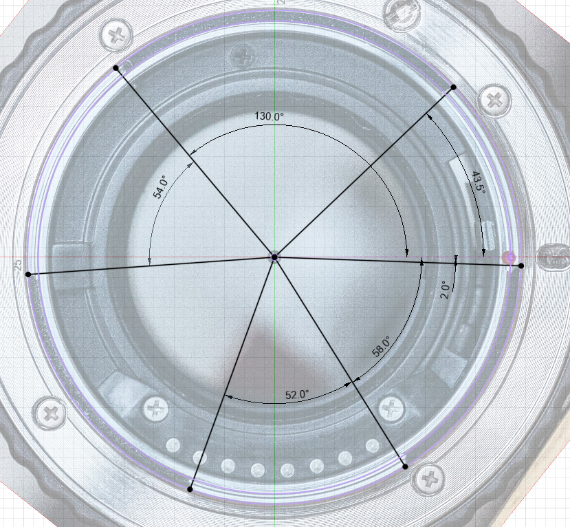
Now our canvas reference comes in really handy, draw radials from the origin out to the outer ring and line them up with the edges of lugs you can see in the canvas. Add dimensions that locate these lines radially with respect to the locking slot:
Next create a new sketch for the locking pin geometry, again on the same plane as the Mount. Project the outer body diameter and the locking pin construction line from the Mount sketch as a reference. Measuring the width of the pin slot can be tricky, so you can measure the diameter of the pin on the camera’s mount instead (2.50mm) and add 0.20mm to it. The other dimensions are estimated from the photo:
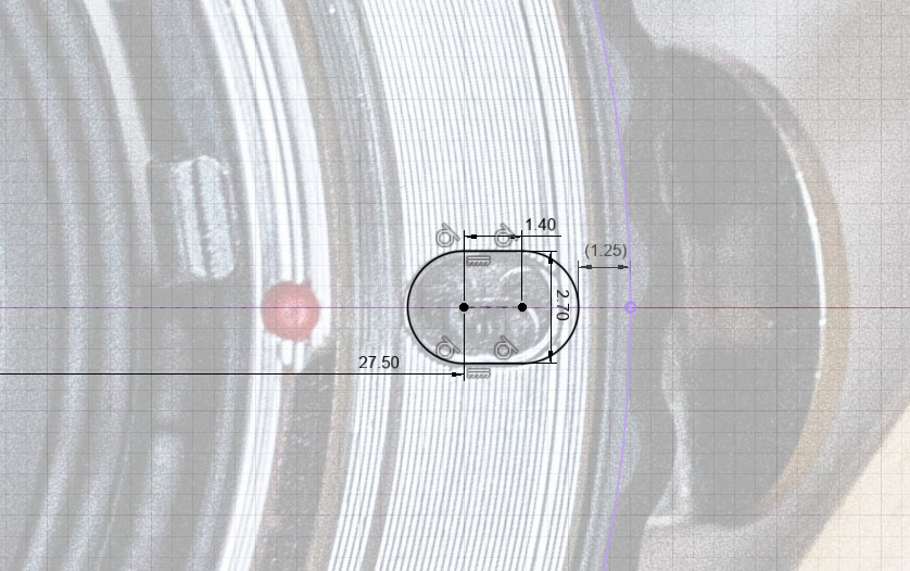
I made the slot extend a little further outwards than the reference design because I noticed that when mounted to a camera, the locking pin sat right at the outer edge of this slot, and I wanted it to be more centred in the slot for more reliable clearance.
I added the (1.25mm) non-driving dimension to check that I had enough wall thickness between the edge of this slot and the outer edge of the body to be 3D-printable. 1.20mm is approximately 3 perimeters with a 0.4mm nozzle.
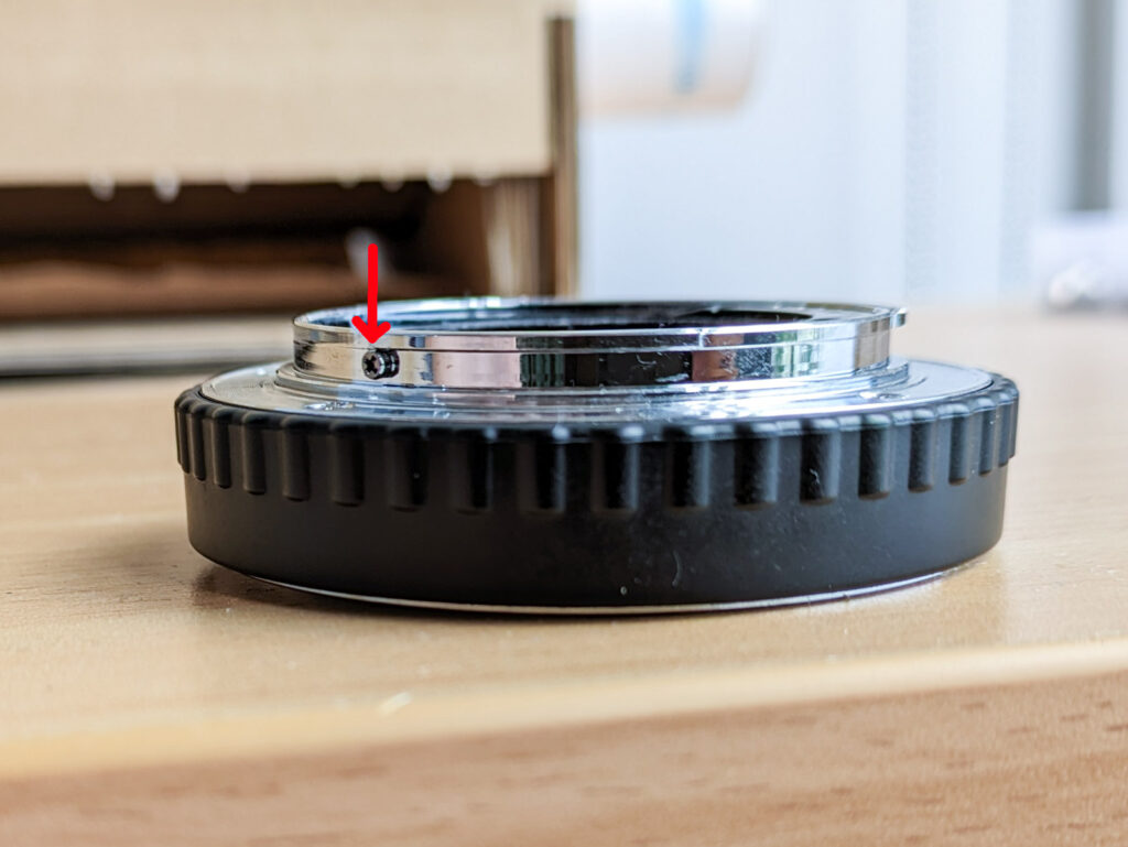
Next I created a sketch with a line in it to mark the angle where the red alignment marking dot should appear (on this lens mount this happens to be exactly in line with the locking pin slot, as shown in the photo above, but this is unusual).
Next I created a sketch to model the “stop screw”. This is a little screwhead found on the outside face of the nose, which is designed to collide with the mount lugs in the camera if you attempt to rotate the lens beyond the point where the locking pin would deploy. Without this feature the lens could spin a full 360 degrees on the camera.
Not all lens mounts use a stop screw in the lens, some have the stop feature in the camera mount instead which a bayonet lug on the lens will crash into. In this case you’ll find that a bayonet lug on the lens will have a leading edge which is straight instead of being smoothly filleted into the nose, so that there is a well-defined edge for the camera’s stop feature to collide with.
I define this stop screw the same way as the mounting lugs, using the outer diameter of the lugs and the outer diameter of the nose, and with lines located relative to the locking screw slot using angular dimensions:
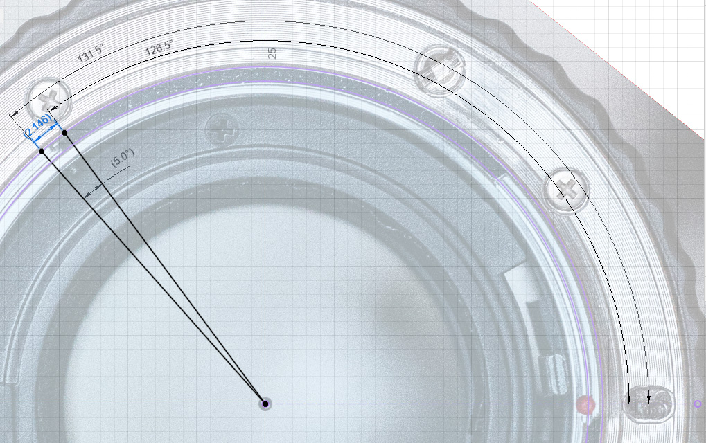
The two angles shown here are 131.5 degrees, which defines how far underneath the mounting lug the screw extends, and 126.5 degrees, which defines how far beyond the edge of the lug the screw extends.
The first angle, 131.5 degrees, determines how much “over-lock” we can achieve when mounting the lens – how far we can rotate the lens beyond the point where the locking pin drops into it. We need to make sure that this angle is not so large that it restricts the lens rotation so that the locking pin can’t reliably drop into the pin slot. Ideally, if we hold down the eject button on the camera, rotate the lens past the locking position against the stop screw, and release the eject button, the camera’s locking pin will just barely catch on the edge of the pin slot and so not fall into it, we’ll have to turn the lens back a fractional amount for it to deploy. This test ensures that we have some non-zero clearance, so that in normal operation the pin can reliably fall into the slot before we hit the stop screw.
The second angle needs to be large enough that the stop screw doesn’t block the lugs from the camera during the initial stage of pushing the lens into the camera for mounting. Here I’ve set it to give the stop screw an effective width of about 2.1mm, because I know this width will be strong, and this didn’t interfere with mounting.
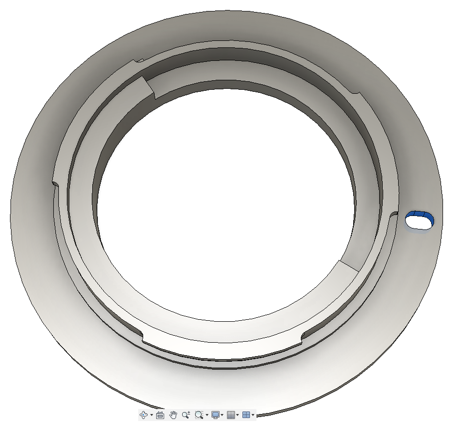
We’re nearly done with sketching, but this lens is unusual in that it has a mechanical aperture lever to link the camera with the lens. The camera has a post which fits into a trench in the back of the lens, and it moves this post to push against the corresponding lever in the lens. You can see the receiving lever here next to the red dot:
We need to model a corresponding cavity in our design, or else the camera’s lever will collide with the lens and the lens will not mount. When mounting the lens, the camera’s lever will drop into this clearance zone, then as we rotate and lock the lens it’ll travel over towards the receiving lever (clockwise from this photo’s perspective) and push against the side of it.
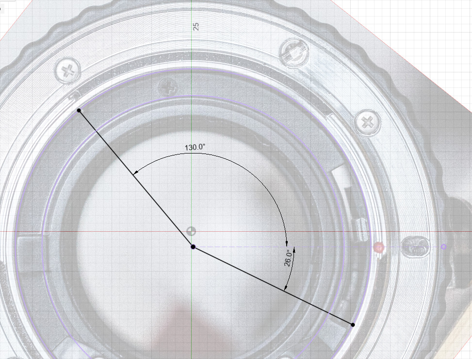
In my sketch the diameter of this slot is defined by the inner radius of the nose on the outside, and the radius of the light portal in the inside. I then defined the position of the radials relative to the locking pin slot like so:
Finally we’re ready to start extruding to create some actual bodies.
I begin by extruding everything in the Mount sketch (except the light portal in the centre) downwards by an arbitrary 2mm to give my mount a base and define the face of the mounting flange that will touch the camera’s mount.
Because of the orientation of my sketches, I have to extrude this in the negative direction, or else my mount will come out mirrored. The lens mounting flange ends up lying in the design origin’s XY plane.
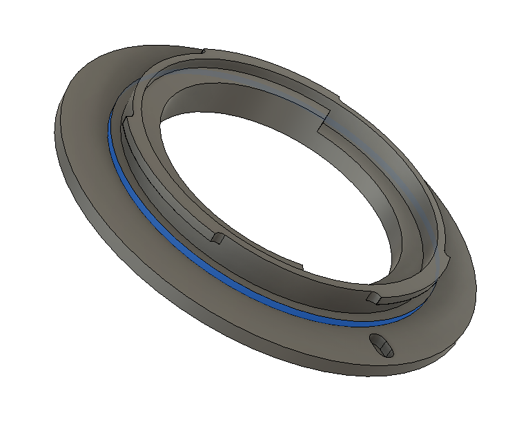
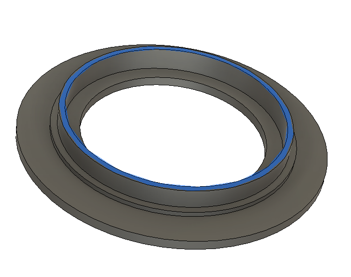
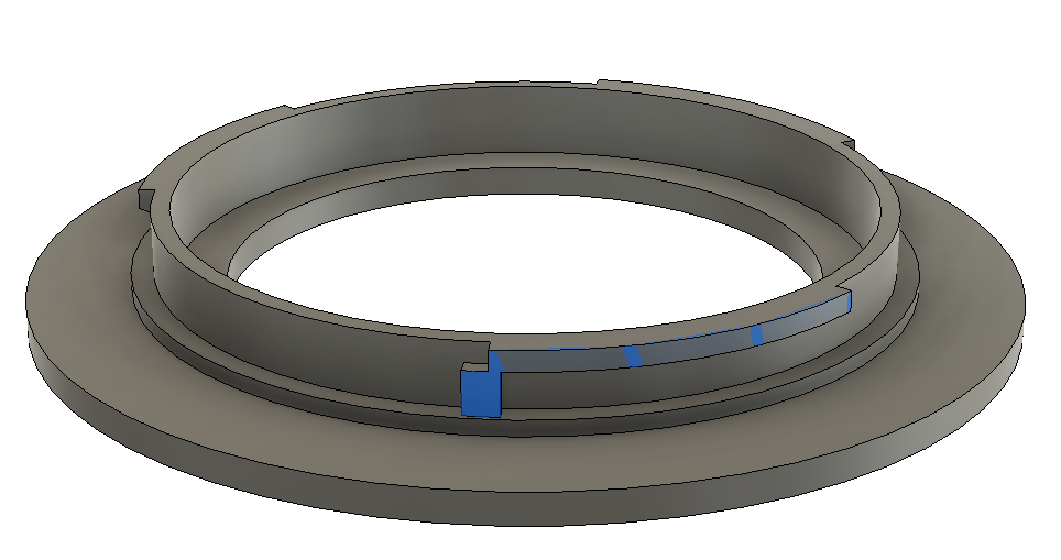
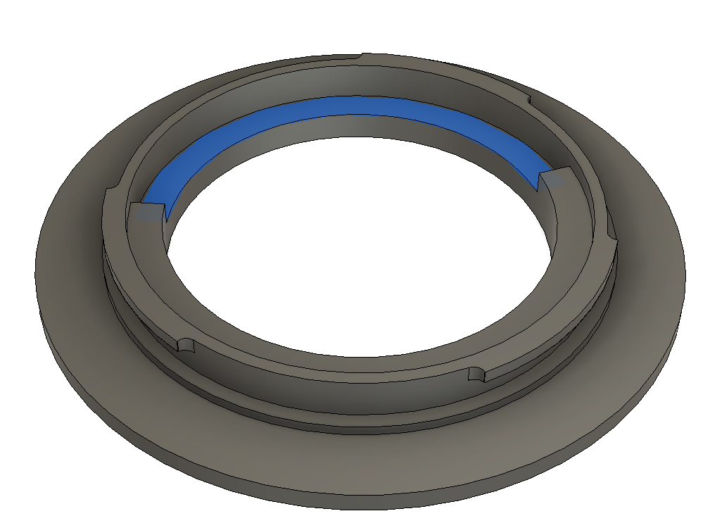
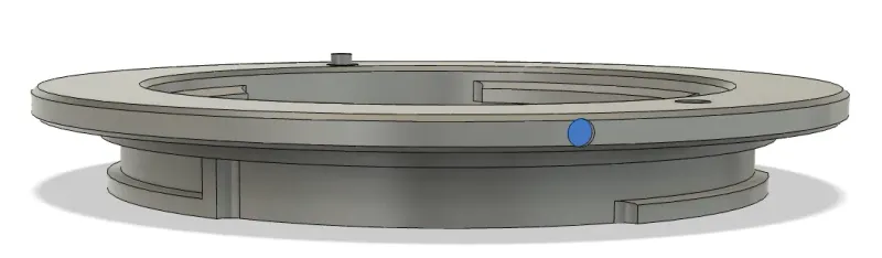
Next I measure the height of the lateral locating ring on my reference mount, above the flange surface (the ring highlighted blue here):
I find it to be 1.00mm tall, so I extrude that ring upwards by 1.00mm on my model. Next I measure the height of the nose (the height between the flange and the top of the lens’ metal extrusions) and find it to be 5.00mm tall, and I make that extrusion. That brings me to this point:
Now from my mounting lugs sketch, I extrude those three lugs downwards from the tip of the nose by a distance that I measure to be 1.2mm to match the reference mount. I extrude the “stop screw” segment upwards to touch the bottom of the mount lugs. That brings me to this point, with the “stop screw” highlighted in blue:
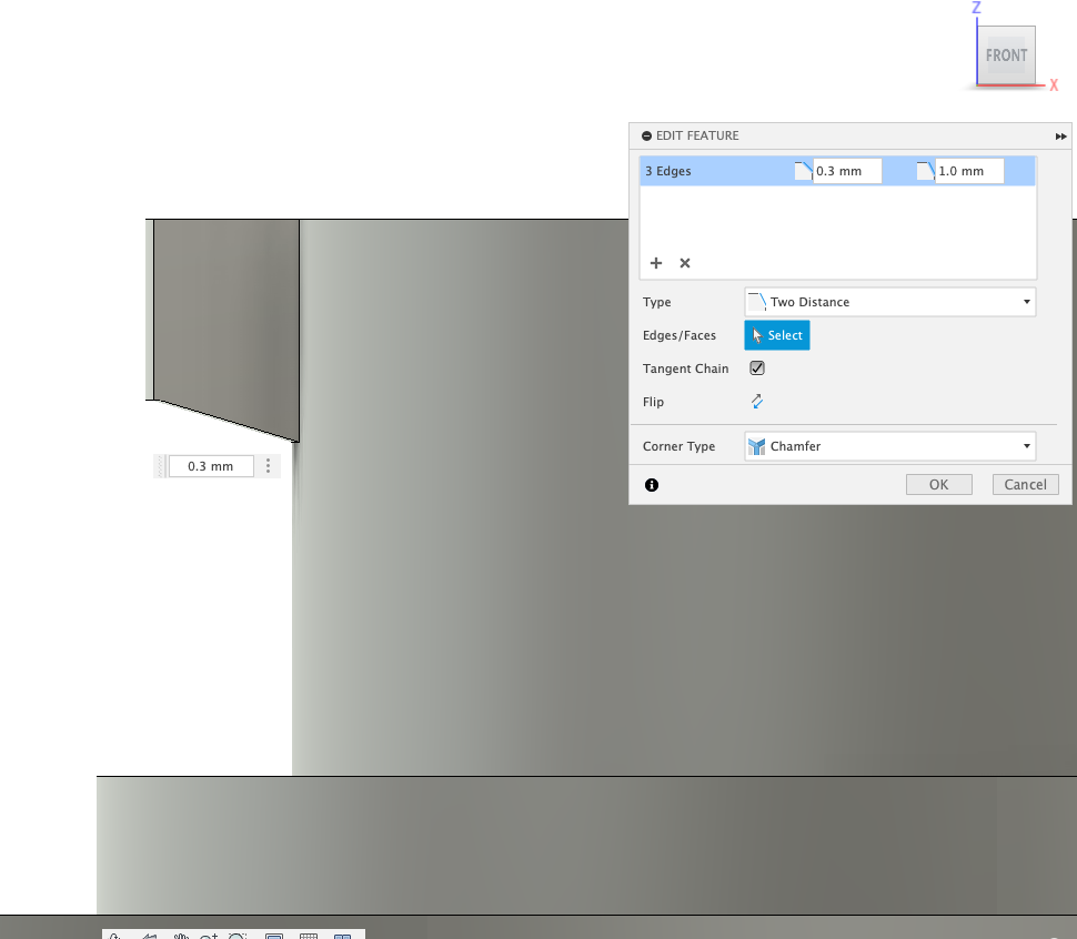
We need to add some features to these lugs to improve printability. I’m planning to print the lugs without supports, so they will be unsupported overhangs when printed. Unsupported overhangs work best when the overhang is not very large, so in order to reduce the width of this unsupported overhang I add a chamfer to the bottom of the three lugs which has a height of 0.3mm and a width as large as possible. This spreads the width of the overhang over a height of 3 x 0.1mm printed layers, such that each overhang is only 0.3mm wider than the previous layer:
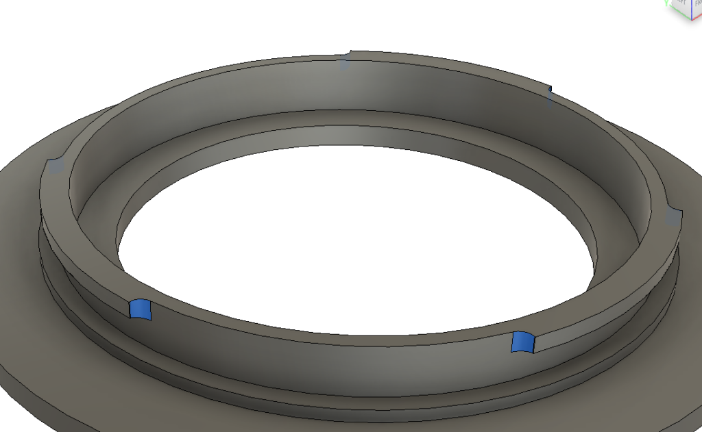
And I add 1mm fillets (blue) where the lugs join the nose to strengthen the lugs and to reduce the tendency for them to warp upwards during printing when printed in ABS:
After adding those fillets, re-visit the alignment of the resulting body with your reference photo. The fillets may make the lugs too wide compared to the reference, which you can adjust the bayonet lugs sketch to fix.
Next we need to deal with clearances for objects within the inner perimeter of the nose. For most lenses this will just be the electronic contacts that come from the camera which we want to avoid rubbing against. But for this Sony A lens we also have to dodge the aperture lever (Nikon F has one of these too).
Let’s examine the contacts on the reference mount first:
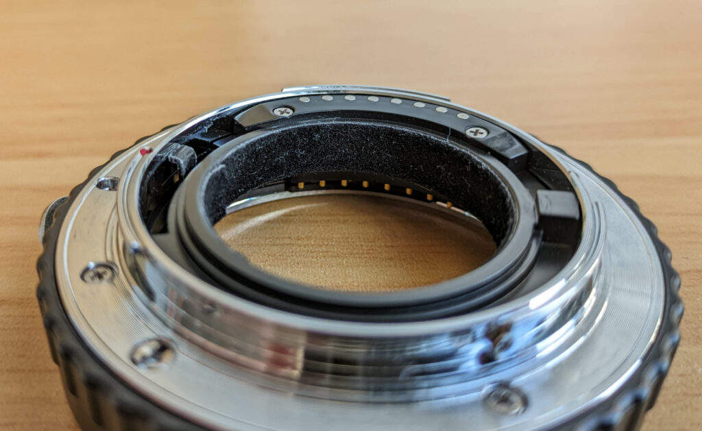
The “contact block” is that black plastic piece at the top of the image with the silver pins on it. During mounting, the contact pins from the camera will sweep around, hit the little black plastic ramp at the start of the contact block, travel up that ramp and scrub across the contact block until they stop on their assigned contact.
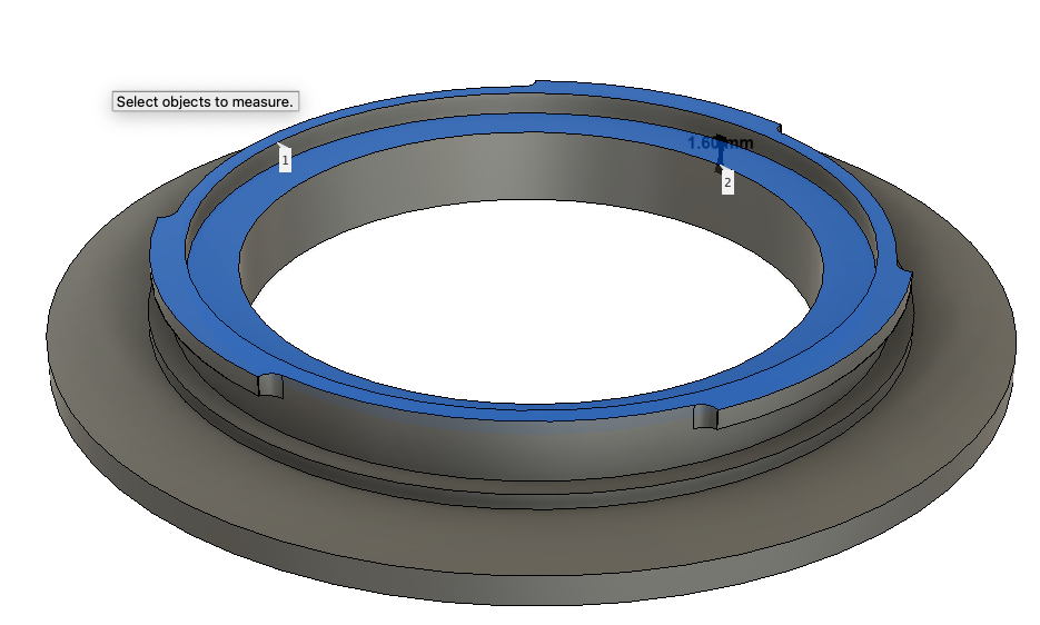
We know that the camera’s contacts could not possibly touch the vertical surface of the contact block before the ramp begins, because if they did they would be crashing into the side of it, and mounting the lens would destroy the contacts in the camera. So we can use the bottom of this ramp as our reference depth for our keepout plane. I use this measurement to create a “contact keepout plane” offset downwards from the top of the nose by 1.60mm.
Now I can extrude the annulus between the inside of the nose and the light cavity upwards until it meets this plane, and the camera’s contacts will never touch it regardless of what angle we mount the lens at:
We desire this ring to exist in our final design because it greatly increases the thickness of the nose across most of its height, which increases its strength.
Next I measure the depth of the trench that the reference mount uses to accept the aperture lever from the camera, and I find the bottom of it to be about 3.8mm below the top of the nose. I round this depth up to 4.00mm. I then use my lever trench sketch to cut a slot to that depth:
Finally, I cut the locking pin slot straight through the mount to the other side. Making this a through-hole helps with testing the mount on the camera, because it allows you to see where the pin ends up being positioned within the slot when mounted to the camera. In my final design I edited the depth of this hole to be 1.60mm, about 0.30mm deeper than the locking pin from the camera is tall.
Time to print!
Now it’s time to print the adapter for testing. I printed in eSUN ABS+, with 0.1mm layer height, 0.4mm nozzle diameter, 3 perimeters, infill 10% rectilinear. I used PrusaSlicer/SuperSlicer’s “standard” perimeter generator because I’ve had strength issues with thin walls when printing the mount using Arachne.
SuperSlicer’s option to print “only one perimeter on top surfaces” comes in really handy because it allows the top layer of the 1.2mm-thick nose to include some infill in the centre, instead of being printed as 2 concentric perimeters with gap-fill (as the rest of the layers of the nose are). This helps to stitch together the concentric perimeters by running crosswise to them.
Once printed, measure the diameter of the as-printed lateral locating ring:
For ABS you’ll find that this diameter ended up substantially smaller than you designed because the whole print shrunk after printing. Other filaments like PLA or PETG have less shrink, but still experience some.
You don’t want to have to chase this shrink by modifying your dimensions in Fusion to compensate for it, that quickly gets out of hand and won’t be portable to other filaments. Instead, measure the as-designed diameter (let’s say 49.90mm) and the as-printed diameter (let’s say 49.65mm) to calculate a shrink factor to input into the slicer, like so:
SuperSlicer – In Filament Settings set Shrinkage to 49.65 / 49.90 * 100 = 99.5%
PrusaSlicer – On the build plate, unlock the scale factor on your model and scale it in X and Y (but not Z) to 49.90 / 49.65 * 100 = 100.5%
This scale factor can vary slightly depending on the geometry of your prints, so you may need to tune it +-0.2% between different objects.
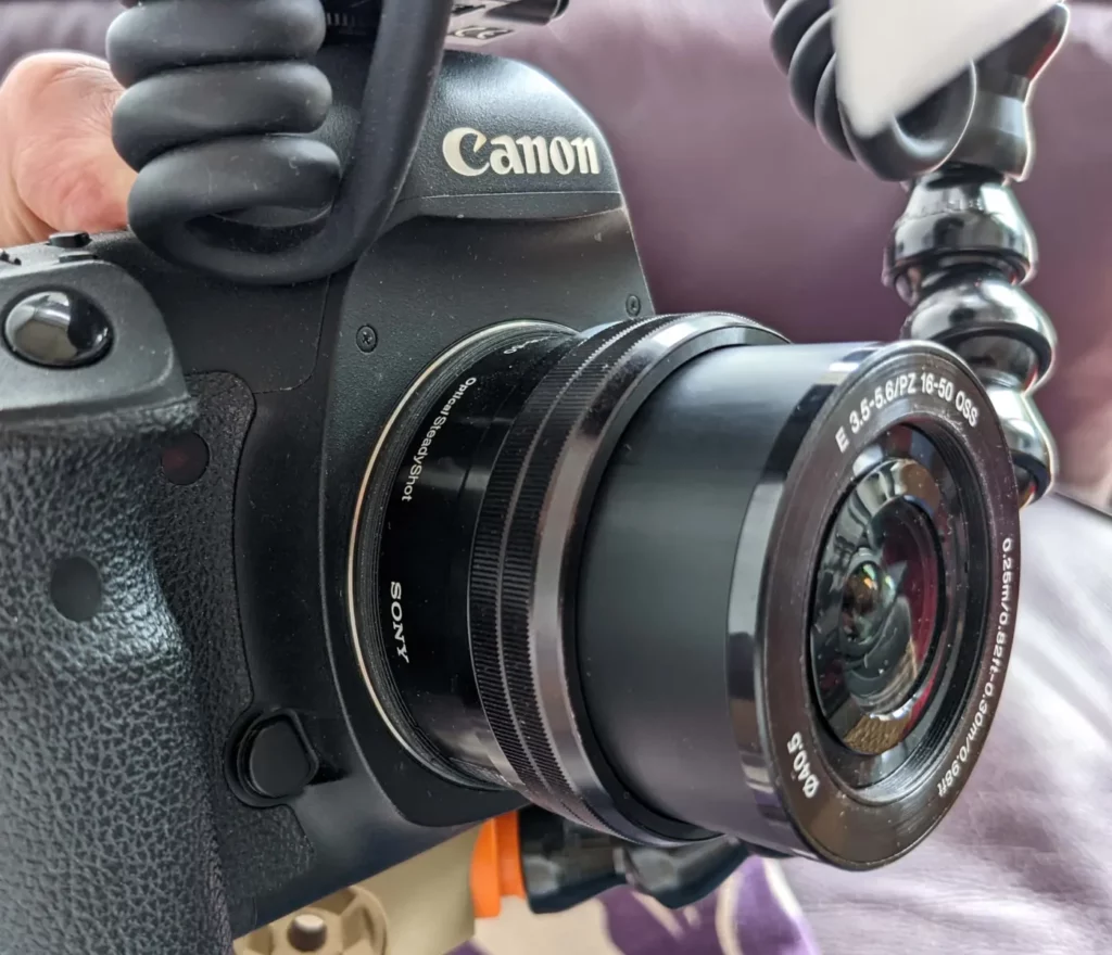
Reprint with the new shrink factor, and now you can test out your adapter on the camera.
Here are some troubleshooting steps to take if it doesn’t fit:
- Will not push down fully or easily into the camera’s mount
- The lateral locating ring is too wide. Check the as-printed dimension of the lateral locating ring against your reference, taking at least two measurements 90 degrees apart to account for ovality/skew in your print.
- Lots of lateral slop when pushed into the camera, but not rotated yet to engage the lugs
- The lateral locating ring is too small. Try bumping up the diameter by 0.10mm.
- Pushes fully into the camera, but impossible to rotate to lock, or resistance to rotation is high
- The bottom edge of the mounting lugs on the nose is too low. Even with perfect measurements during design, this can be caused by the printability chamfer that was added underneath the lugs. Raise the bottom edge of the lugs by 0.2mm and try again.
- Pushes fully into the camera, rotates fine, but can’t rotate enough for the locking pin to reach the slot
- The stop screw extends too far underneath its mount lug, adjust this angle and try again.
- Pushes fully into the camera, rotates fine, but locking pin skips over the slot, or the locking pin deploys but you cannot hear a crisp “click” from it like you do with a regular lens
-
You may have a burr around the edge of the locking pin slot. If you stick a hobby knife like an x-acto knife into the slot and run it vertically around the edge of the slot you can trim off any burr, then test again. Do not attempt to bevel the top edge of the slot, because this will assist the locking pin in climbing out of it.
If it still does not lock properly then the slot may be too narrow, bump the width up by 0.2mm and try again.
- Camera contact pins or aperture levers can be observed touching the printed surface on their sides or tips
- Increase clearances for keep-out zones
Download the example
You can download the Fusion 360 model I created for the Sony A mount here
Go further
With these skills you can now do crazy things like creating a forbidden adapter from Sony FE mirrorless lenses to Canon EF DSLRs:
https://www.printables.com/model/205667-sony-fee-lens-to-canon-efef-s-camera-macro-adapter
Or an adapter for a cheap $20 microscope for macro photography at 4x magnification:
Full transparency, I have not fully read through your entire report on this, but I will once I have time. I love this stuff. Admittedly, a lot of it is over my head, but I try my hardest to follow and learn what I can. I came across your report as I was searching for ways to mount an old Canon XL mount lens to either an e-mount or even an EF/RF mount. The issue I am seeing is nobody has really attempted it and most conversations ended back in 2014. There are forums where people are asking the same questions, but nothing transpires after someone says “its not possible”. My issue is I am not an engineer. I have tried, but I just dont have some of the knowledge to properly do this. I am a professional creative. The bulk of my work is design, photo and video. But I love to tinker and love learning which makes things like adapting old lenses to modern tech is so appealing to me. But also frustrating at the same time because so much of it is over my head. Is there any chance you have messed around with the lens from the Canon XL1? I feel like it would work on a Sony FX30 since its mirrorless and a cropped sensor. Im just curious of what kind of results this would yield. If you happen to have time to maybe exchange some emails, I would love to pick your brain on this subject a bit more if you’re willing. I myself, dont have a ton of time, but projects like this keep me sharp(ish) and helps my creative processes. If you dont have time, I fully understand. Thank you for your time and I hope to hear back from you.
That camcorder has a 1/3″ sensor size, which is a crop factor of 7 compared to full frame, it’s the size of a sensor in a modern iPhone.
So the image produced by it will only fill a tiny spot in the middle of your frame, only 20% of the width of a 1.5x crop frame. It’s likely the coverage will be higher when zoomed in. It’d be more at home on a Pentax Q (5.6x crop), but it’ll be usable on the Sony, the biggest issue being the size of the image in the viewfinder.
It should be physically possible to adapt it to mirrorless cameras though.
Your extension tube for the microscope objective is amazingly cool. It printed perfectly and I’m so excited to use it. Thanks so much! You rock!