
Regular fans for 3D printers have just two wires, power and ground, and we vary the average supply voltage to the fan using PWM to change its speed.
However 4-wire computer fans like Noctuas are different, these fans expect a steady 12V power supply and a separate 5V PWM signal to set their speed. Check the pinout of your fan’s connector here:
https://noctua.at/en/what-pin-configuration-do-noctua-products-use
The steady 12V supply is easy, on the BTT Octopus we can just set the voltage selection jumper on one of the always-on fan headers (like FAN6) to 12V, and connect the power and ground of the fan to that fan connector like normal. Note that you don’t need to use a fan header for this, any source of 12V you have handy will do fine.
However to add a 5V PWM signal for speed control we have to do something a little extra. On the Octopus, like on most 3D printer boards, the PWM fan control switches a MOSFET which either connects or disconnects the negative (ground) pin of the fan header. If we connect this negative pin to the PWM input of the fan, then when the MOSFET is closed the PWM pin will be pulled to ground by the MOSFET and the fan will see 0V, and when the MOSFET is open the pin will be pulled up by the fan’s internal 5V pull-up, and the fan will see 5V. This is exactly what we need.
On a PWM fan header (e.g. FAN5), first remove all of the voltage selection jumpers (to avoid the output being pulled up to an erroneous and possibly damaging voltage through the onboard green LED). Then connect the PWM pin (the “negative” pin of that fan header) to the fan’s PWM input so:
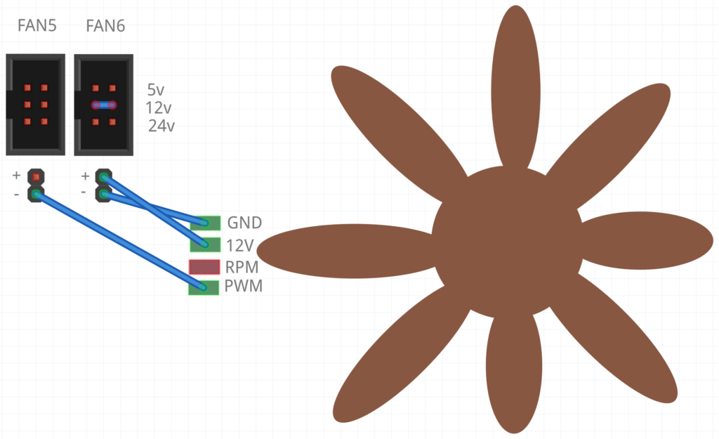
Note that the PWM signal is inverted (i.e. setting 0% fan speed will actually give us 100%), so we also need to invert the pin definition to fix this by adding a “!” in front of the pin name in Klipper like so:
[temperature_fan exhaust_fan]
# 4-pin computer PWM exhaust fan - FAN5
pin: !PD15
control: pid
pid_Kp: 40
pid_Ki: 0.2
pid_Kd: 0.1
max_power: 1.0
min_speed: 0
max_speed: 1
shutdown_speed: 0.0
kick_start_time: 2.0
target_temp: 50
# The thermistor that measures the temp for this temp-controlled fan:
sensor_type: ATC Semitec 104GT-2
sensor_pin: PF5
min_temp: 5
max_temp: 100
gcode_id: C

# The official PC fan spec calls for 21-28kHz PWM frequency, but my Noctua at least was happy with the default 100Hz software PWM. So if your controller doesn't support hardware_pwm then try leaving these two lines out:
hardware_pwm: True
cycle_time: 0.00004 # 25 kHz
Monitoring fan RPM
You can also add monitoring so that Klipper can measure the fan’s RPM, using the RPM pin on the fan. To do this, connect the fan’s RPM pin to the signal pin of a spare endstop connector (diag connector) on the Octopus. For example, here I’ve connected it to DIAG3:
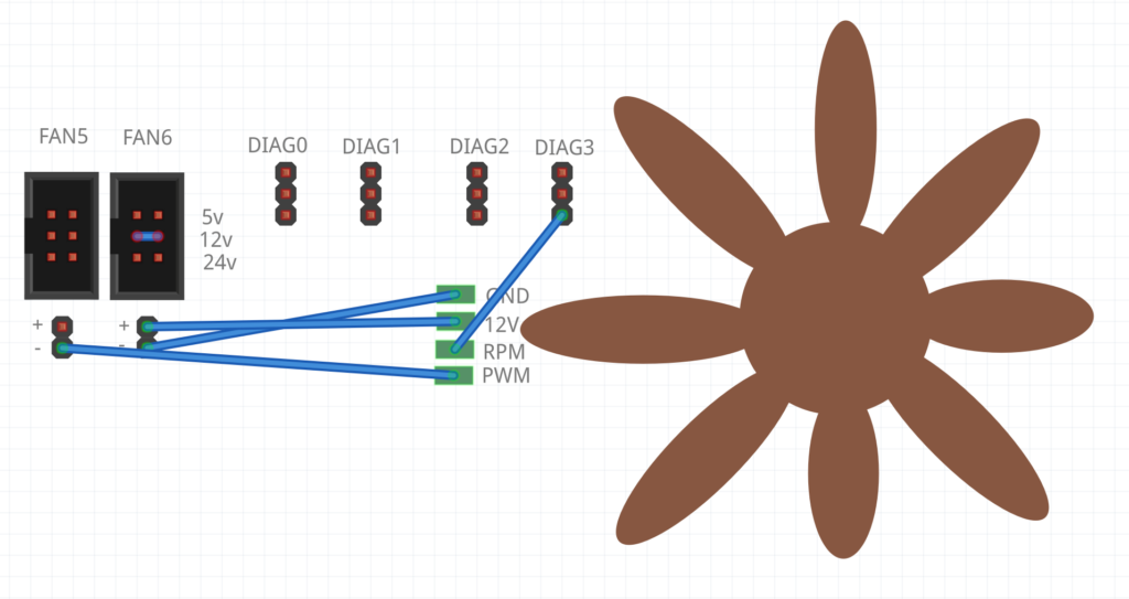
Looking at the pinout documentation for the Octopus, you can see that DIAG3’s signal pin is called PG11:
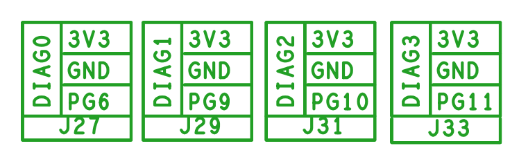
So in my temperature_fan configuration I added this code, with a ^ added in front of the pin name to enable the pull-up on DIAG3’s signal pin:
# RPM monitoring:
tachometer_pin: ^PG11
tachometer_ppr: 2
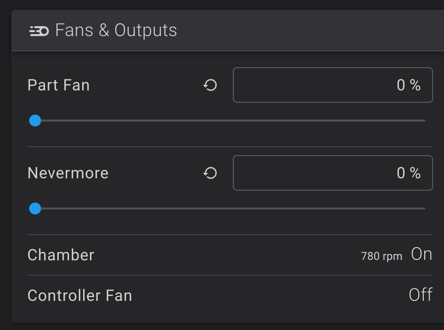
Now you’ll see the measured RPM appearing in the Fans & Outputs section of Fluidd:
Hey Nick,
Thanks for this info, its helped me to get my Sanace 4-wire PWM exhaust fan running smooth and quiet and efficiently.
Just wondering how did you come up with those PID numbers? I can’t seem to work out how to tune PID with a fan instead of a heater.
Cheers Mate 🙂
Cheers 🙂
There are a bunch of generic guides on the net that explain the role the P, I and D terms take in the resulting behaviour.
I had to tune P upwards from its initial value and D downwards, because without this it didn’t even reach the temperature setpoint. It took a bit of trial and error though!
If I had to tune it in again from scratch I’d probably set I and D to zero, then tune up P until it oscillates around the setpoint, then tune up I and D to damp the oscillation.
Hi Nick,
I get “pin PF3 used multiple times in config” error for the heater bed thermistor pin.
Anyway to workaround it?
Hi Nicholas,
Do you happen to fly Racing drones and live in Sydney?
I used to fly racing drones but I’m in New Zealand 🙂
I’m the original author of Betaflight/Cleanflight’s “Blackbox” flight logging feature
I planned to work on these same setup instructions for my Octopus board owners FB group, but you have already got it worked out. I am going to provide a link in the group for other members.
How to monitor fan rpm? https://www.klipper3d.org/Config_Reference.html#fan
I’ve added a section which explains how to do this now!
it doesnt need any
tachometer_poll_interval: 0.0015
settings?
No it doesn’t, as when this is omitted it just uses the default value, which works fine.
What role does PF5 sensor pin play in your setup. because when i have this enabled it doenst work and when i disable it the fan blows but klipper shows an error message.
That’s the thermistor I’m using to measure the temp for this temperature-controlled fan. If you don’t want your fan to be temp-controlled, don’t use [temperature_fan], use something like [fan_generic] and remove everything from the config you don’t see here:
https://www.klipper3d.org/Config_Reference.html#fan_generic
If you do want it to be temp controlled, be sure to set it to the right pin to match your thermistor.
i would like to use your configuration for the controller_fan.
As i am totaly new to klipper can you somehow help ww with this.
The board i use is octocpus pro 446 and the fan for the controller is configured (alias) to PD12
For a controller fan you can do something like this:
`[controller_fan controller_fan]
pin: !PD12
kick_start_time: 0.5
fan_speed: 0.6
shutdown_speed: 1.0 # Blast the fan if an error is triggered
heater: heater_bed
hardware_pwm: True
cycle_time: 0.00004 # 25 kHz
This will turn on to 60% speed when the heatbed is turned on. For more tweaking of the behaviour, see the docs:
https://www.klipper3d.org/Config_Reference.html#controller_fan
Hi there,
I tried the same as you did only with PD14
[temperature_fan exhaust_fan]
# 4-pin computer PWM exhaust fan – FAN4
pin: !PD14
control: pid
pid_Kp: 40
pid_Ki: 0.2
pid_Kd: 0.1
max_power: 1.0
min_speed: 0
max_speed: 1
shutdown_speed: 0.0
kick_start_time: 2.0
target_temp: 50
# The thermistor that measures the temp for this temp-controlled fan:
sensor_type: ATC Semitec 104GT-2
sensor_pin: PF5
min_temp: 5
max_temp: 100
gcode_id: C
# The official PC fan spec calls for 21-28kHz PWM frequency, but my Noctua at least was happy with the default 100Hz software PWM. So if your controller doesn’t support hardware_pwm then try leaving these two lines out:
hardware_pwm: True
cycle_time: 0.00004 # 25 kHz
where I wired the PWM to the PD14 Pin and power from FAN6+
however I do not seem to get power of the FAN6+ how can I turn that on or off?
FAN6 and FAN7 are always on, they can’t be switched off, their voltage is set using the jumpers above them.
Are you sure the fan isn’t just being set to zero speed because your temp is already lower than your target temp of 50?
I tried changing the tems and see in the klipper interface that it should run, but the fans do not run actually. I tried removing the ! as well and restarted. but also no fan action. Will the fans fry if +/- are wrongly connected?
They can be fried by that, yes.
I did the same, on my setup only the pins are different ones (Octopus Pro).
In Mainsail (yes, I use RatOS which is based on Mainsail) the fan seem to work fine, but it stops when I set the target higher than the current and starts spinning when the target is lower than the current temperature. It actually has to be the other way around…What is wrong?!
You need an exclamation mark at the start of the pin name.
Of course I have the exclamation mark. As I said, I just have different pins, the rest is the same. Also double and triple checked the wiring….
I reread your original comment, you’re wanting your cooling fan to work backwards. If your target temperature is lower than the current, the fan should be on, not off, since the fan needs to cool things down to that temperature.
You can just remove the exclamation mark if you really want it to work the other way.
I tried but the fan has anomalous behavior, it turns on at low speed then when the temperature sensor approaches the target the fan turns on at maximum for a second and then repositions itself at low speed. It remains cyclical, slow then maximum for a second and then slow again.
I tried it liky you describe here but my fan’s are always running at 100% 🙁
after some more ready i found a text on Noctua website where they say thr PWM should be 0-5V and not ground..~~?
so I also tried changing the fan-connector to 5V and connecting that pin to plus but no change also
Ground is 0V, and the fan has an internal pull-up to 5V, so the PWM signal is already correct using my scheme.
Double check your connections.
Great write up, just what I was looking for ever since I built a chamber for my printer. Appreciate the time you put into explaining this. The ground being switched was the important bit I was missing. Cheers!
Hi sir:
Thanks for your sharing. It works on my Ratrig Vcore!
But there’s a little problem. While I setup the speed to 80%, I get the speed shows 24000rpm, while I setup the speed to 100%, the speed shows 16000rpm.
What’s the problem.
Thanks in advance.
You for sure do not have a 24,000rpm fan. Did you actually wire up the rpm sensor? If not it’ll be triggered by random noise.
If your fan has a different number of pulses per revolution (ppr) make sure that’s configured correctly.
I have the same issue. Using a Sanyo Denki 9GAX0412P3S001 25000RPM fan on an Octopus 1.1 Board. It will read RPM up to 23900 when at 83%. Above that the RPM reading goes down while the fan still revs up.
Setting tachometer_poll_interval: 0.00001 helps, otherwise it will only read to about 17k for me. I have the feeling the Octopus 1.1 can only handle up to 45k pulses per second or something.
I am having an issue where everything is coded how you explain but the fan will not turn on. I am using the fan as a controller fan as it is in the skirts and for the life of me i can’t figure out why the fan wont turn on.
Check what happens with the fan when you first power your printer on. During boot, the PWM pins float, which should cause the fan to run at 100%. If your fan doesn’t spin even then, your issue is likely to be the power and ground connections for the fan rather than the printer config.
Hi Nick,
thank you for this insight. I adapted your information to a MKS SKIPR and it works great!
bye Sebastian
I have recently used an extra Bambu lab aux fan in another klipper printer with a spider v1.0 board. I took basically what you did and ported it to the other board. The only thing is that the tach pin on the diag pin isn’t giving an RPM reading. I also seem to hit max speed (by sound) at 70%. What might I be missing?
Hi, do you not have to put a jumper (5V) for the FAN5 to ensure the PWM signal is 5V?
No, the fan itself pulls its PWM pin high, and the printer only alternately connects this pin to ground or allows it to float to the pullup voltage, the printer does not drive any voltage onto this pin itself.